The Aperta Door Entry System is a modern, user-friendly solution designed to enhance security and convenience for residential and commercial properties. It combines video monitoring, remote access, and secure locking mechanisms, offering a comprehensive approach to door entry management.
Overview of the Aperta Door Entry System
The Aperta Door Entry System is a comprehensive security solution offering video monitoring, remote access, and secure locking. It includes a door station with a camera, an indoor monitor, and a locking mechanism. The system supports remote communication and door release, enhancing convenience and safety. Designed for residential and commercial use, it integrates advanced features like proximity and keypad access. The system uses Cat5E cabling for reliable connections and is compatible with various power supplies. Its user-friendly interface and robust design make it a versatile choice for modern security needs, ensuring effective control over entry points.
Key Features and Benefits
The Aperta Door Entry System offers high-definition video streaming, enabling clear visitor identification. It features remote door release functionality, allowing users to grant access from any location. The system supports dual authentication methods, including proximity fobs and PIN codes, ensuring enhanced security. With expandable memory for storing user data, it accommodates up to 1000 fobs and PINs in Zone 1 and 10 in Zone 2; Its durable design withstands outdoor conditions, and the monitor provides a user-friendly interface for easy operation. These features collectively ensure a secure, convenient, and scalable access control solution for various applications.

System Components
The Aperta Door Entry System includes a door station with a camera, an indoor monitor, a locking mechanism, and a power supply unit. Cabling connects these components securely.
Door Station and Camera
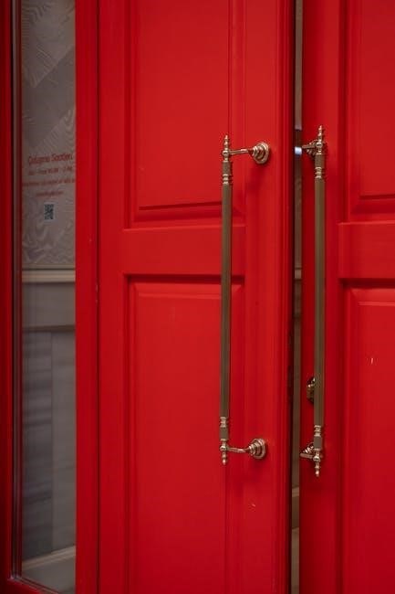
The door station is the external component of the Aperta system, featuring a built-in camera that provides a clear view of visitors. It is typically surface-mounted at a recommended height of 1.5 meters for optimal visibility. The camera is equipped with a sunshield to protect against glare and ensure crisp video quality. Two-way audio communication is supported, allowing users to interact with visitors remotely. The door station connects to the monitor via system cabling, enabling real-time video preview and lock release functionality. Its durable design ensures reliability in various weather conditions, enhancing security and convenience for users.
Monitor and Locking Mechanism
The Aperta system includes an indoor monitor that allows users to view live video from the door station and remotely unlock the door. The monitor is connected to the locking mechanism, which can be programmed to respond to user codes, fobs, or remote commands. The lock mechanism supports both latched and unlatched operation, ensuring secure access control. Technical specifications include DC/AC input compatibility (12-24V) and low power consumption, with standby current at 80mA and operating current at 110mA. The system also features a lock output that switches when activated, ensuring reliable performance.
Power Supply and Cabling Requirements
The Aperta Door Entry System requires a power supply compatible with both DC and AC inputs, ranging from 12 to 24 volts. The system operates efficiently with a standby current of 80mA and an operating current of 110mA when the lock is not engaged. All system cabling, excluding the mains 240vAC supply, is tested with Cat5E UTP PVC cable for reliable performance. Proper cabling ensures clear video transmission, stable communication, and consistent locking mechanism operation. Ensure all connections are secured to avoid interference and maintain system functionality. This setup ensures optimal performance and durability of the door entry system.
Installation Steps
Mount the door station at the recommended height of 1.5 meters. Install the monitor indoors and connect system cabling as per the wiring diagram. Secure all connections properly to ensure reliable functionality.
Mounting the Door Station
Mount the door station at least 1.5 meters above ground for optimal visibility and security. Surface mount the sunshield to protect the camera from direct sunlight. Attach the door station to the sunshield using the provided hex screws. Ensure the camera is pointing towards the visitor’s direction. Properly thread the system cable through the cable entry hole to maintain weather resistance. Tighten all connections firmly to avoid loose wiring. Finally, test the camera and keypad functionality to ensure everything operates smoothly before proceeding with further installation steps.
Connecting System Cabling
Connect the system cabling using Cat5E UTP PVC cable for all low-voltage connections, excluding the 240vAC mains supply. Route the cable from the door station to the monitor, ensuring it is securely fastened to avoid damage. Connect the cables to the designated ports on both the door station and monitor, following the wiring diagram for accuracy. Ensure all connections are tight to prevent signal loss. Power supply cables should be connected to the appropriate DC/AC inputs (12-24V). Double-check all wiring before powering up the system to ensure proper functionality and safety.

Installing the Monitor and Lock
Mount the monitor indoors in a convenient location, ensuring clear visibility. Secure the monitor bracket to the wall using provided screws. Attach the monitor to the bracket, ensuring it is level and firmly fastened. For the lock, install it near the door, aligning it with the strike plate. Connect the lock mechanism to the system’s cabling, following the wiring diagram. Test the lock’s operation to ensure proper functionality. Once installed, ensure all connections are secure and the system is ready for programming. This step completes the physical setup of the monitor and lock components.

System Connections
Connect the door station, monitor, and lock using Cat5E UTP cabling. Adhere to the wiring diagram for proper connections, ensuring all components communicate securely and function seamlessly.
Wiring Diagram and Connections
The Aperta Door Entry System requires precise wiring to ensure proper functionality. Use Cat5E UTP PVC cable for all system connections, excluding the 240vAC mains supply. Connect the door station to the monitor and locking mechanism as per the provided wiring diagram. Ensure the lock output is configured correctly and tested for activation from the monitor. Secure the door station 1.5 meters above ground and align the camera to face visitor entry points. Proper connections ensure seamless communication and reliable operation of the system.
Configuring the Monitor and Lock
Connect the system cables to the monitor’s rear ports as specified in the wiring diagram. Slide the monitor onto its bracket using the hooks to secure it firmly. Configure the lock output on the door station to ensure it activates when the monitor signals. Test the lock mechanism to confirm proper operation. The system operates on 12-24V DC/AC with a standby current of 80mA and 110mA during operation. Use the 4-digit lock release code for remote unlocking, enhancing user convenience and security.
Programming the System
The Aperta system allows programming of user codes, key fobs, and remote access settings. It supports up to 1000 fob/PIN combinations and ensures compatibility with various door configurations.
Setting Up User Codes and Fobs
Setting up user codes and fobs on the Aperta system ensures secure access. Assign unique codes and pair fobs via the monitor interface. The system supports up to 1000 fob/PIN combinations, providing flexibility for multiple users. Enter the programming menu, assign codes, and sync fobs using the provided instructions. Ensure codes are 4-6 digits for optimal security. Proximity tags or key fobs can be programmed for convenience. Always test codes post-configuration to confirm functionality with the lock mechanism; Regularly update codes and fobs to maintain system security and accessibility.
Configuring Remote Access Settings
Configuring remote access for the Aperta Door Entry System allows users to manage door entry from anywhere. Start by connecting the system to your network using the provided IP address and port settings. Ensure your router is configured for port forwarding to enable remote connectivity. Download and install the Aperta mobile app, available for iOS and Android devices. Log in using the system’s credentials and test remote functionality, such as video streaming and lock control. Enable two-factor authentication for added security. Refer to the user manual for detailed steps and troubleshooting tips to ensure a secure and stable remote connection.
Troubleshooting Common Issues
Common issues with the Aperta system include connectivity problems and lock malfunctions. Check all connections and ensure the power supply is stable. Refer to the manual for detailed solutions and reset procedures to restore functionality quickly and effectively.
Resolving Connection Problems
To resolve connection issues in the Aperta Door Entry System, first inspect all cabling for damage or loose connections. Ensure the Cat5E UTP PVC cable is securely connected between components. Verify the power supply is stable and meets the system’s requirements (12-24V DC/AC); Check the monitor and lock connections, ensuring they are properly linked to the door station. If issues persist, refer to the wiring diagram in the manual to confirm all connections are correctly configured. Restarting the system or resetting the monitor may also resolve connectivity problems.
Addressing Lock Mechanism Malfunctions
If the lock mechanism fails to respond, first ensure the power supply is stable and meets the system’s requirements (12-24V DC/AC). Check the cabling connections between the door station, monitor, and lock for any damage or loose links. Verify that the lock output on the door station is switching correctly when activated by the monitor. If the issue persists, test the lock mechanism independently to confirm it is functioning properly. Resetting the system or consulting the wiring diagram may help resolve the malfunction. If problems remain, contact a professional for further assistance.