
Manual transmissions, detailed in numerous guides and manuals, rely on precise component interaction.
Understanding the shift linkage – often visually represented in diagrams – is crucial for both operation and repair, as highlighted by online resources.
What is a Manual Transmission?
Manual transmissions, often detailed in automotive repair manuals and online guides, represent a method of gear changing where the driver directly selects gears using a shift lever. Unlike automatic transmissions, they don’t utilize hydraulic pressure or a torque converter to shift.
These systems, frequently illustrated in shift linkage diagrams, rely on a driver’s input to engage different gear ratios. This control allows for a more connected driving experience and, often, greater fuel efficiency. Understanding the fundamentals, as found in field manuals and instructional resources, is key to appreciating the mechanics involved.
The Role of Shift Linkage
Shift linkage serves as the crucial mechanical connection between the driver’s shift lever and the internal gear selection mechanisms within the manual transmission. Detailed shift linkage diagrams showcase this system’s complexity. It translates the driver’s movements into precise actions, engaging the correct gear for desired speed and torque.
Without a functioning shift linkage, as explained in various service manuals, the driver cannot effectively control the vehicle. Online resources and repair guides emphasize its importance, highlighting how even slight adjustments can dramatically impact shifting performance. Proper operation ensures smooth and accurate gear changes.

Components of a Manual Transmission Shift Linkage System
Diagrams illustrate key parts: the shift lever, linkage rods, pivot balls, transmission shift fork, and shift rail – all working together for gear selection.
Shift Lever
The shift lever, prominently featured in any manual transmission shift linkage diagram, serves as the driver’s primary control for selecting gears. Its design varies, but fundamentally, it translates the driver’s hand movements into mechanical actions. Diagrams clearly show how the lever’s position corresponds to specific gear engagements within the transmission.
Online resources and service manuals detail the lever’s connection points, often illustrating pivot points and the linkage it activates. Understanding the lever’s geometry, as depicted in diagrams, is essential for diagnosing shifting issues and performing repairs. The lever’s internal mechanisms, though sometimes complex, are readily explained through detailed visual guides.
Shift Linkage Rods
Shift linkage rods, clearly illustrated in a manual transmission shift linkage diagram, are the crucial connectors transmitting motion from the shift lever to the transmission. These rods, often metal, precisely transfer the driver’s input. Diagrams showcase their routing and connection points, vital for understanding the system’s operation.
Free PDF manuals emphasize the importance of rod integrity; bends or damage directly impact shifting accuracy. Online resources detail how to inspect rods for wear, referencing diagrams to pinpoint correct positioning. Proper rod length and secure connections, as shown visually, are paramount for smooth gear changes and avoiding internal transmission damage.
Pivot Balls and Sockets
Pivot balls and sockets, prominently featured in a manual transmission shift linkage diagram, facilitate smooth rotational movement within the linkage. These components allow for flexibility, compensating for slight misalignments. Service manuals highlight their location and function, often with exploded views for clarity.
Diagrams reveal how wear on these balls and sockets introduces “play” into the system, leading to imprecise shifting. Online forums discuss replacement procedures, referencing diagrams to ensure correct orientation. Free guides emphasize inspecting these parts during troubleshooting, as they are frequent failure points impacting gear selection, as detailed in available manuals.
Transmission Shift Fork
The transmission shift fork, clearly illustrated in a manual transmission shift linkage diagram, is the internal component directly engaging with the synchronizers to select gears. Repair guides emphasize its critical role in smooth gear changes. Diagrams showcase its connection to the shift rail and the precise movements required for each gear.
Automotive repair websites detail how a bent or worn shift fork causes grinding or difficulty selecting gears. Manuals often include diagrams illustrating proper fork alignment. Online communities discuss identifying fork issues through visual inspection, referencing diagrams to pinpoint potential damage and the need for replacement, as found in free PDF manuals.
Shift Rail
The shift rail, prominently featured in a manual transmission shift linkage diagram, is the linear component transferring motion from the shift linkage to the shift forks. Service manuals detail its precise path within the transmission. Diagrams illustrate how the rail’s movement, guided by selector rods, dictates gear engagement.
Automotive repair websites explain that a damaged or misaligned shift rail results in imprecise shifting. Online forums discuss diagnosing rail issues by referencing diagrams and checking for binding. Free PDF manuals often include exploded views showing the rail’s interaction with other components, aiding in repair and understanding its function within the system.
Types of Manual Transmission Shift Linkage
Shift linkage systems – direct, cable, or hydraulic – are clearly depicted in diagrams. Manuals and guides illustrate each type’s unique layout and operational principles for effective repair.
Direct Linkage Systems
Direct linkage systems, frequently showcased in automotive repair manuals and online diagrams, represent the most straightforward approach to connecting the shift lever to the transmission. These systems utilize rigid rods and pivot points, offering a precise and tactile feel for the driver. Diagrams clearly illustrate how movement at the shift lever directly translates to the shift forks within the transmission.
These diagrams often highlight the precise geometry of the linkage, emphasizing the importance of proper alignment for smooth and accurate gear selection. Troubleshooting guides frequently reference these diagrams when diagnosing shifting issues, such as imprecise engagement or difficulty finding specific gears. The simplicity of direct linkage makes understanding its operation, via a diagram, relatively easy.
Cable-Operated Systems
Cable-operated systems, commonly depicted in service manuals and automotive websites, employ flexible steel cables to transmit motion from the shift lever to the transmission. Diagrams illustrate how the cable housing and inner cable work in conjunction, allowing for greater flexibility in shift lever placement. These systems are often used in front-wheel-drive vehicles where direct linkage is impractical.
Detailed diagrams showcase the cable routing and attachment points, crucial for proper adjustment and troubleshooting. Repair guides emphasize checking for cable stretch or damage, often visible in diagrams highlighting potential failure points. Understanding the cable’s path, as shown in a diagram, aids in diagnosing issues like sloppy shifting or difficulty engaging gears.
Hydraulic Systems
Hydraulic systems, less common but present in some performance applications, utilize fluid pressure to actuate the shift forks within the transmission. Manuals and repair guides detail these systems, often featuring complex diagrams illustrating the master cylinder, lines, and slave cylinder arrangement. These diagrams are essential for understanding fluid flow and component interaction.
Unlike cable or direct linkages, hydraulic systems offer precise and consistent shift feel. Diagrams highlight the hydraulic lines’ routing and the location of crucial components like accumulators and pressure regulators. Troubleshooting guides emphasize checking for leaks and proper fluid levels, visually aided by detailed system diagrams available on automotive repair websites.

Detailed Diagram Breakdown
Shift linkage diagrams, found in service manuals and online, visually represent component placement and connections. Understanding these diagrams is key to identifying parts and their function.
Identifying Key Components in a Diagram
Manual transmission shift linkage diagrams, readily available through online resources and repair guides, showcase essential parts. These include the shift lever, the driver’s control point, and linkage rods connecting it to the transmission. Pivot balls and sockets facilitate movement, while the shift rail and shift fork internally engage gears.
Color-coding, often used in these diagrams, highlights different circuits or components for clarity. Locating these elements within a diagram allows for a better understanding of how the entire system operates, aiding in troubleshooting and repair. Free PDF manuals often contain detailed illustrations.
Understanding Shift Pattern Representation
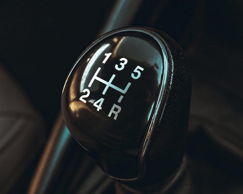
Shift linkage diagrams commonly depict shift patterns – visual guides illustrating gear positions. These patterns, often resembling an “H” or other configurations, show how the lever moves to select each gear. Understanding this representation is vital for interpreting the diagram and diagnosing shifting issues.
Online forums and service manuals frequently utilize these patterns. The diagram’s clarity helps visualize the mechanical connection between lever movement and gear engagement. Searching for specific manuals can reveal detailed explanations of these patterns, aiding in both repair and comprehension of the transmission’s operation.
Color Coding in Shift Linkage Diagrams
Shift linkage diagrams often employ color coding to enhance clarity and understanding; Different colors typically represent distinct components – rods, pivot balls, or sockets – simplifying identification during repair or troubleshooting. This visual aid, found in service manuals and online guides, streamlines the process of locating specific parts;
Consistent color schemes across diagrams allow for quicker comprehension. Manuals frequently include a legend explaining the color assignments. Utilizing these color cues, alongside the shift pattern, facilitates accurate diagnosis and efficient component replacement, as detailed in automotive repair websites.

Common Issues with Shift Linkage
Shift linkage diagrams reveal potential failure points; worn parts or damage to rods and pivot balls cause imprecise shifting, requiring careful inspection and repair.
Worn Pivot Balls
Pivot balls, clearly visible in a shift linkage diagram, are a frequent source of issues. Over time, these components experience wear due to constant motion and stress. A diagram helps pinpoint their location for inspection. Worn pivot balls create excessive play within the linkage, leading to imprecise shifting and a vague feel.
This looseness translates to difficulty selecting gears and can even cause grinding. Online resources and service manuals emphasize the importance of regularly checking these balls for wear or damage. Replacement is often necessary to restore proper shift feel and prevent further damage to other linkage components, as illustrated in repair guides.
Bent or Damaged Linkage Rods
Shift linkage rods, prominently featured in any shift linkage diagram, are susceptible to bending or damage from road impacts or accidental contact. A clear diagram aids in identifying the correct rod orientation and assessing for any visible deformation. Even slight bends can significantly affect shift accuracy and smoothness.
Damaged rods introduce binding or resistance, making gear selection difficult. Online forums often discuss the consequences of bent rods, including potential transmission damage. Repair guides detail how to inspect these rods and, if necessary, replace them to restore the intended shift geometry, ensuring proper function as shown in schematics.
Loose Connections
A shift linkage diagram clearly illustrates all connection points within the system. Loose connections – at pivot balls, sockets, or rod ends – are a frequent cause of imprecise shifting. These looseness introduces unwanted play, making it difficult to engage the desired gear accurately.
Service manuals emphasize the importance of regularly checking and tightening these connections. Online resources and repair guides demonstrate how to identify loose components. Ignoring loose connections can lead to increased wear on other parts and potentially cause shifting failures, as visualized in detailed exploded views found in manuals.
Cable Stretch or Damage
Cable-operated systems, depicted in a shift linkage diagram, are susceptible to cable stretch over time. This stretch increases the free play in the system, resulting in sloppy shifting. Damage, like fraying or kinking, further compromises cable function.
Manuals and online repair guides detail how to inspect cables for wear and proper operation. A diagram helps pinpoint the cable’s routing and attachment points. Replacement is often necessary when stretch or damage exceeds acceptable limits. Ignoring these issues can lead to complete shifting failure, as illustrated in troubleshooting sections of service manuals.

Troubleshooting Shift Linkage Problems
Shift linkage diagrams are invaluable for diagnosing issues; identifying component locations aids in pinpointing the source of difficult shifting or grinding gears.
Diagnosing Difficult Shifting
Difficult shifting often stems from issues within the shift linkage system, and a detailed diagram becomes an essential diagnostic tool. Begin by carefully studying the diagram to understand the intended movement of each component – rods, pivot balls, and the transmission shift fork.
Compare the diagram’s representation of proper linkage positioning with the actual state of your vehicle’s system. Look for any visible deviations, such as bent rods or loose connections. Online forums and repair guides frequently showcase these diagrams, aiding in identifying potential problem areas.
Pay close attention to the shift pattern representation on the diagram; discrepancies here can indicate internal transmission issues or linkage misalignment. A clear understanding, facilitated by the diagram, is key to effective troubleshooting.
Identifying Grinding Gears
Grinding gears during shifts can signal a problem within the manual transmission, and a shift linkage diagram aids in pinpointing the cause. The diagram illustrates how the shift fork engages each gear; improper engagement, often due to linkage issues, leads to grinding.
Examine the diagram to trace the linkage path to the gear experiencing difficulty. Look for any bends, looseness, or wear in the rods and pivot points along that path. Service manuals, readily available online, provide detailed diagrams and troubleshooting steps.
Confirm the shift linkage is correctly adjusted according to the diagram’s specifications. Incorrect adjustment prevents full gear engagement, resulting in that unpleasant grinding sound.
Checking for Linkage Play
Excessive linkage play contributes to imprecise shifting and can be diagnosed using a shift linkage diagram as a reference. The diagram visually demonstrates the intended movement of each component. Inspect each connection point – pivot balls, sockets, and rod ends – for looseness while referencing the diagram’s expected positions.
With the vehicle safely supported, attempt to move the shift lever through its range of motion. Observe the corresponding movement in the transmission via the linkage, comparing it to the diagram. Any noticeable slack or delayed response indicates play.
Online forums and repair guides often detail acceptable play tolerances, aiding in accurate assessment.

Repairing and Replacing Shift Linkage Components
Repairing or replacing components requires referencing a shift linkage diagram for correct assembly and adjustment, ensuring proper gear engagement and smooth operation.
Tools Required for Shift Linkage Repair
Successfully repairing a manual transmission shift linkage demands a specific toolkit. Beyond standard wrenches and sockets – crucial for disassembling components – specialized tools become essential. A shift linkage diagram is paramount for identifying parts and understanding assembly. Pivot ball removal tools are often necessary, alongside pliers for cable work.
Penetrating oil aids in loosening corroded parts, while a torque wrench ensures proper tightening. Grease is vital for lubricating pivot points. Accessing manuals and online guides, as suggested by numerous resources, will detail specific tool requirements for your vehicle’s unique linkage system. Safety glasses and gloves are also non-negotiable.
Replacing Pivot Balls and Sockets
Replacing worn pivot balls and sockets restores precise shifting, referencing a shift linkage diagram is key for correct placement. Begin by disconnecting the old components, often requiring a specialized removal tool. Thoroughly clean the socket bores before installing new parts, ensuring a snug fit.
Lubricate the new pivot balls with grease before insertion. Reassembly should mirror the diagram, verifying full range of motion. Online resources and service manuals detail specific procedures for various vehicles. Proper installation prevents premature wear and ensures smooth gear changes, as detailed in available guides.
Adjusting Cable-Operated Linkage
Adjusting cable-operated linkage requires referencing a shift linkage diagram to confirm correct geometry. Begin by loosening the cable adjustment point, typically near the transmission. Shift through all gears, verifying full travel and proper engagement. Tighten the adjustment until neutral is accurately centered, preventing gear selection issues.
Fine-tune the cable tension for smooth, precise shifts. Online forums and repair guides offer vehicle-specific instructions. Incorrect adjustment can lead to grinding or difficulty selecting gears. Regularly inspect the cable for stretch or damage, consulting diagrams for proper routing and securing.
Safety Precautions When Working with Shift Linkage
Always disconnect the battery and support the vehicle securely before working on the shift linkage, referencing a diagram for component locations and safe removal.
Disconnecting the Battery
Before commencing any work on the manual transmission shift linkage – and especially when referencing a diagram to understand its complexities – always disconnect the vehicle’s battery. This crucial safety step prevents accidental electrical shorts or activation of vehicle systems during the repair process. Locate the negative terminal, typically black, and carefully remove the cable, securing it away from the terminal.
Consulting a service manual or online guides (like ManualLib.com) can provide specific instructions for your vehicle model. This precaution minimizes the risk of damage to electronic components and ensures a safe working environment, allowing focused attention on the mechanical aspects of the shift linkage system.
Supporting the Vehicle Properly
When working beneath a vehicle to access the manual transmission shift linkage – even while referencing a detailed diagram – securely supporting it is paramount. Never rely solely on a jack! Always use jack stands, positioned on designated reinforced areas of the vehicle’s frame; Consult your vehicle’s service manual or online repair guides for proper jacking points.
Ensure the vehicle is stable and level before beginning any work. A collapsed vehicle can cause severe injury or damage. Prioritize safety; a stable platform allows focused attention on understanding and repairing the shift linkage system, as illustrated in available manuals and resources.
Using Appropriate Safety Gear
When diagnosing or repairing a manual transmission shift linkage – aided by a comprehensive diagram – personal protective equipment (PPE) is essential. Wear safety glasses to shield your eyes from debris. Gloves protect your hands from sharp edges and fluids. Sturdy footwear prevents injuries from dropped tools or vehicle components.
Consider wearing long sleeves and pants for added protection. Referencing repair manuals and online guides won’t prevent physical hazards. Prioritize your well-being; proper gear ensures a safe working environment while tackling this automotive task, as detailed in numerous service guides.
Resources for Manual Transmission Information
Online forums and service manuals offer detailed diagrams of shift linkage systems, aiding understanding and repair, alongside countless free PDF manuals available online.
Online Forums and Communities
Automotive enthusiast forums are invaluable resources for deciphering complex manual transmission shift linkage diagrams. Members frequently share detailed images, troubleshooting advice, and even custom modification experiences. These communities often host dedicated threads specifically addressing shift linkage issues, allowing users to pinpoint problems and find solutions collaboratively.
Many forums feature searchable databases of technical information, including exploded views and schematics. Experienced mechanics and DIY enthusiasts readily offer guidance, interpreting diagrams and explaining component functions; Accessing these platforms provides a wealth of practical knowledge beyond what’s found in standard repair manuals, fostering a supportive learning environment for all skill levels.
Service Manuals and Repair Guides
Factory service manuals are the definitive source for understanding manual transmission shift linkage diagrams. These guides provide detailed, vehicle-specific illustrations showcasing component placement, assembly procedures, and torque specifications. Repair guides, often available in both print and digital formats, supplement manuals with step-by-step instructions and photographic aids.
Locating the correct manual – often searchable online via brand and model – is crucial. Diagrams within these resources clearly identify each linkage part, aiding in diagnosis and repair. They also outline proper adjustment procedures, ensuring optimal shifting performance. Utilizing these guides minimizes errors and promotes accurate restoration of the shift linkage system.
Automotive Repair Websites
Automotive repair websites offer a wealth of information, including accessible manual transmission shift linkage diagrams. Many platforms host user-submitted guides, forum discussions, and video tutorials detailing linkage repair and adjustment. These resources often feature exploded views of the linkage, clearly labeling each component for easy identification.
Searching for specific vehicle makes and models yields targeted diagrams and troubleshooting advice. Websites like ManualLib.com provide access to millions of manuals, including those with detailed linkage schematics. While valuable, always cross-reference information with official service manuals to ensure accuracy and safety during repairs.

Advanced Shift Linkage Systems
Advanced systems, like short shifters, often require specialized diagrams for installation and understanding. Upgrades and custom fabrication necessitate detailed schematics for proper function.
Short Shifter Kits
Short shifter kits dramatically alter the throw length, impacting the shift linkage geometry. Installation often requires referencing a detailed diagram to ensure correct component placement and adjustment. These kits frequently involve replacing existing linkage parts with shorter alternatives, necessitating a clear understanding of the original system’s layout.
A comprehensive diagram illustrates how the shortened linkage affects the shift pattern, reducing travel distance between gears. Proper installation, guided by these visuals, prevents binding or imprecise shifting. Online forums and repair guides often showcase exploded views and step-by-step instructions, vital for successful modification. Careful attention to the diagram is paramount for optimal performance.
Shift Linkage Bushing Upgrades
Shift linkage bushing upgrades aim to eliminate play and improve precision, often visualized through detailed diagrams. Worn bushings contribute to sloppy shifting, and replacement requires understanding the linkage’s articulation points. A clear diagram showcases bushing locations and proper orientation during installation.
These upgrades typically involve swapping rubber bushings for firmer polyurethane alternatives. The diagram helps identify the correct bushing size and type for each position within the linkage system. Online resources and service manuals provide exploded views, aiding in disassembly and reassembly. Accurate referencing of the diagram ensures a solid, responsive shift feel.
Custom Shift Linkage Fabrication
Custom shift linkage fabrication demands meticulous planning, heavily reliant on a comprehensive diagram. This process often arises from modifying existing vehicles or building unique setups. A detailed diagram is essential for accurately determining rod lengths, pivot point locations, and overall geometry.
Fabrication requires precise measurements and welding skills, guided by the diagram to ensure proper function. Considerations include minimizing binding and maximizing leverage. Online forums and repair guides offer examples, but a custom diagram tailored to the specific application is paramount. Successful fabrication results in a tailored, precise shifting experience.